Made by
A
Ayan Malik, AS-B3
M
Muhammad Raza, AS-B4
S
U
N
L
O
C
K
M
O
R
E
Code Editor: adjust parts of code according to your own preferences.
Debugging: a human-based service which AI has not replaced.
Interactive Simulator: test the circuit before actually deploying it.
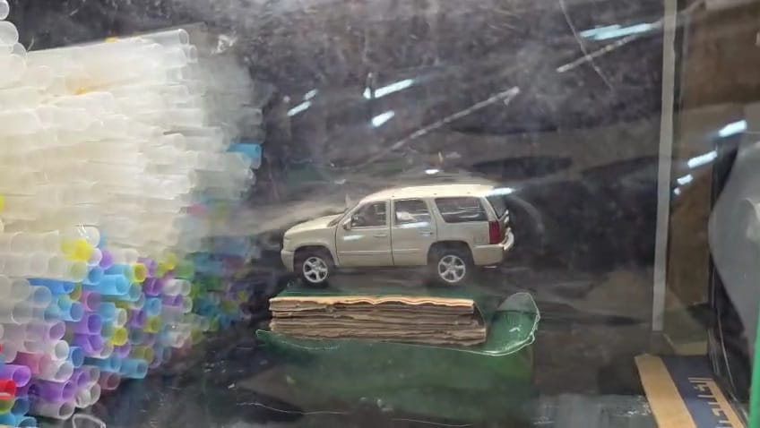
A small-scale wind tunnel project testing sedan and Formula One car models to compare aerodynamics, studying drag, lift, thrust, and weight using Bernoulli’s Principle and Newton’s Laws.
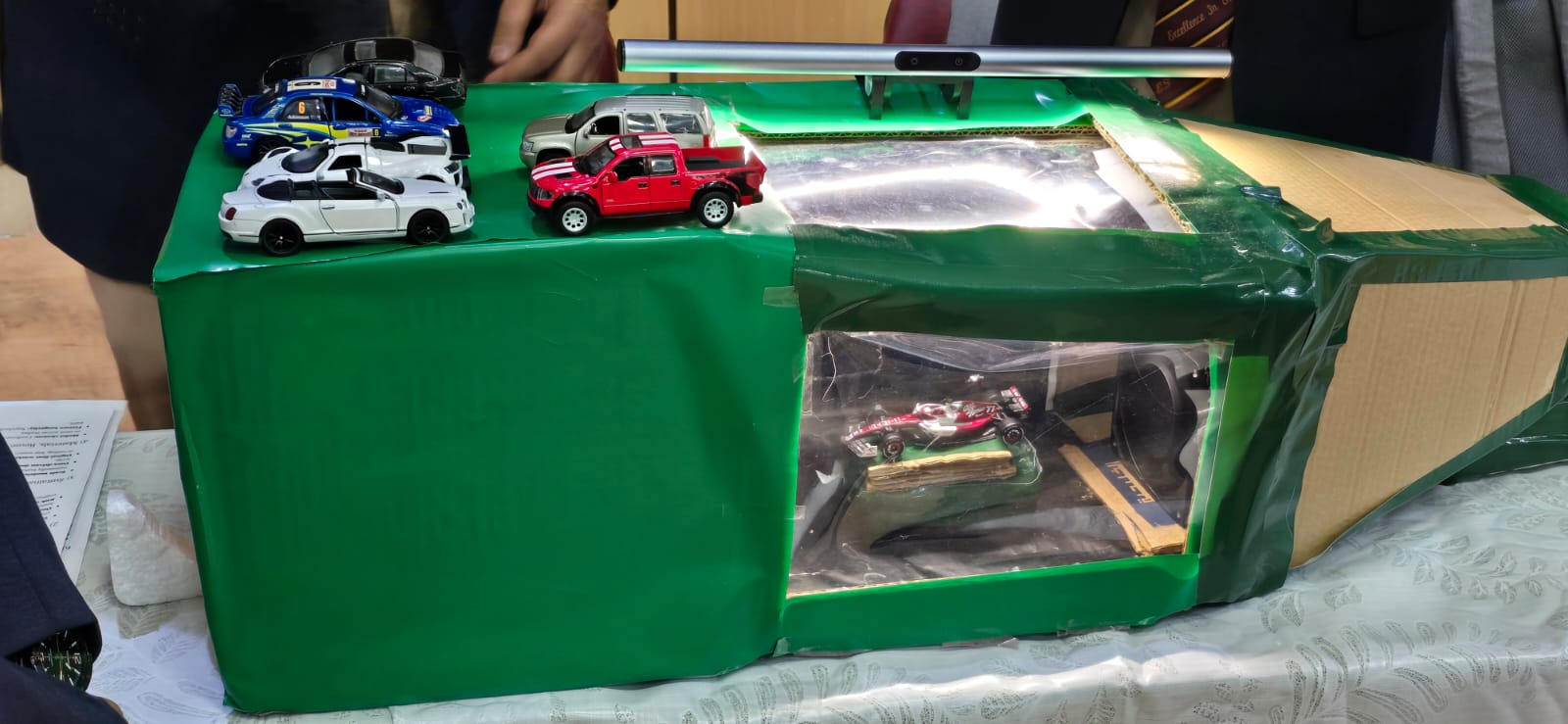
Sketch the overall design of the wind tunnel, including the intake, contraction cone, test section, and diffuser. Choose dimensions proportional to the size of the test models to ensure smooth airflow.
Construct the tunnel body using sturdy cardboard panels. Cut and assemble rectangular sections for the intake, test chamber, and outlet, sealing all edges with glue or tape to prevent air leakage.
Attach a household fan securely at the rear end of the tunnel to act as the air source. Ensure the airflow direction pulls air through the tunnel rather than pushing, to reduce turbulence near the models.
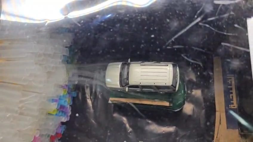
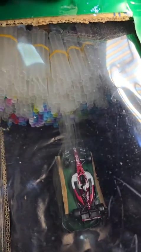
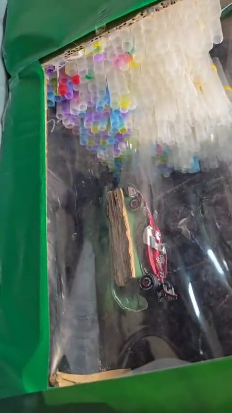
Place a tightly packed bundle of drinking straws at the intake section. This straightener eliminates air swirls and helps maintain laminar flow before air enters the test section.
Build a narrowing cardboard section between the intake and the test area to accelerate airflow, following the principle of continuity (A?V? = A?V?).
Construct a clear rectangular chamber using acrylic sheets for visibility. Mount the car model at the center, ensuring it is stable and level with the airflow path.
Attach an expanding section at the outlet end of the tunnel to slow the airflow smoothly and minimize turbulence as it exits the system.
Connect thin tubes or straws near the intake to release smoke from incense sticks or glycerin vapor. This will make the airflow visible around the test models.
Power on the fan and observe the airflow using the smoke streams. Note areas of laminar and turbulent flow, wake formation, and lift or downforce differences between the sedan and Formula One models.
Record observations through photos or video. Compare smoke patterns, drag behavior, and flow separation points to evaluate aerodynamic efficiency.
No code available