Made by
W
U
N
L
O
C
K
M
O
R
E
Code Editor: adjust parts of code according to your own preferences.
Debugging: a human-based service which AI has not replaced.
Interactive Simulator: test the circuit before actually deploying it.
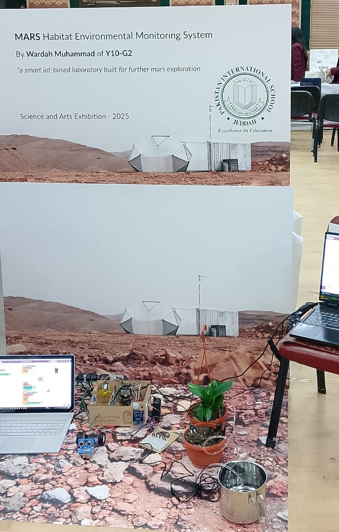
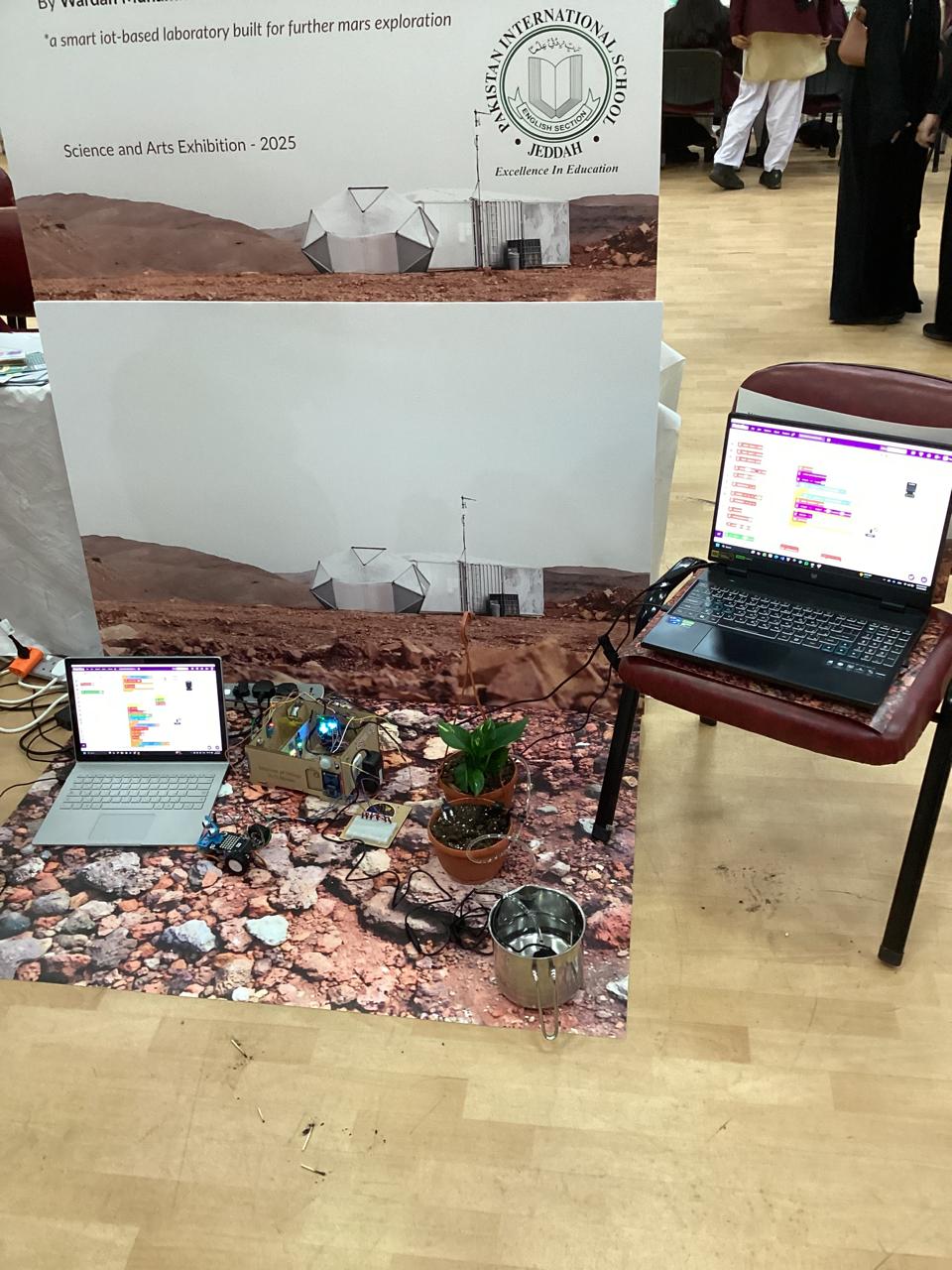
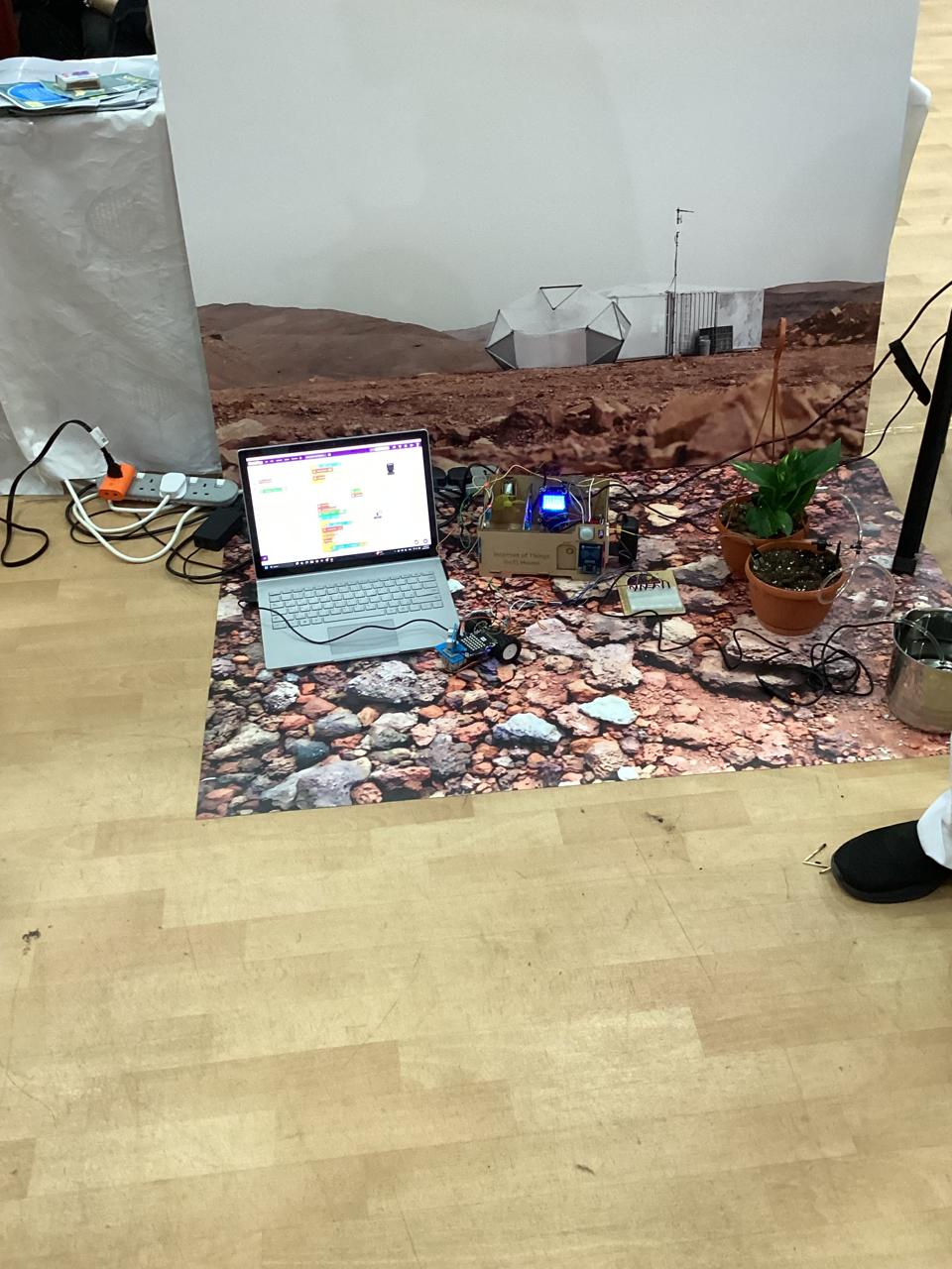
A smart IoT-based laboratory built for further Mars exploration.
Defined the problem: Simulating a controlled environment inside a Mars habitat.
Identified key parameters to monitor: temperature, humidity, light, flame, and soil moisture.
Planned automated responses: alarms, fan activation, smart plug control, door opening, and light activation.
Used the IoT House simulation model from STEMpedia.
Components used:
DHT11 (Temperature & Humidity Sensor)
LDR (Light Sensor)
Flame Sensor
Soil Moisture Sensor (for plant irrigation monitoring)
Fan (for ventilation)
Smart Plug
Relay Module (to control AC appliances)
Quarky Module
Quarky Expansion Board (for extra connectivity)
Jumper Wires
Pictoblox (to code)
Breadboard
Connected all sensors and actuators to the Quarky Expansion board.
Verified proper pin mapping and power supply for each component.
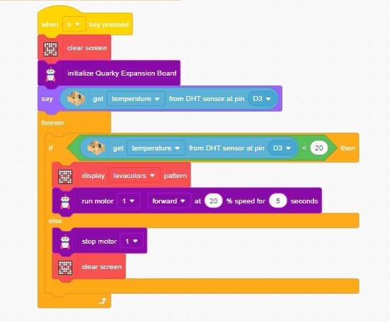
Wrote the Python block code to:
Continuously read data from all sensors.
Trigger alarms, fans, or smart plugs if readings go beyond safe levels.
Automate actions like:
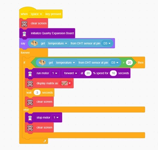
- Turning on the fan when temperature levels are high.
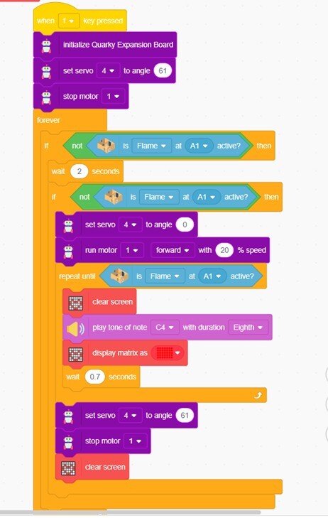
- Activating the security system when a fire is detected.
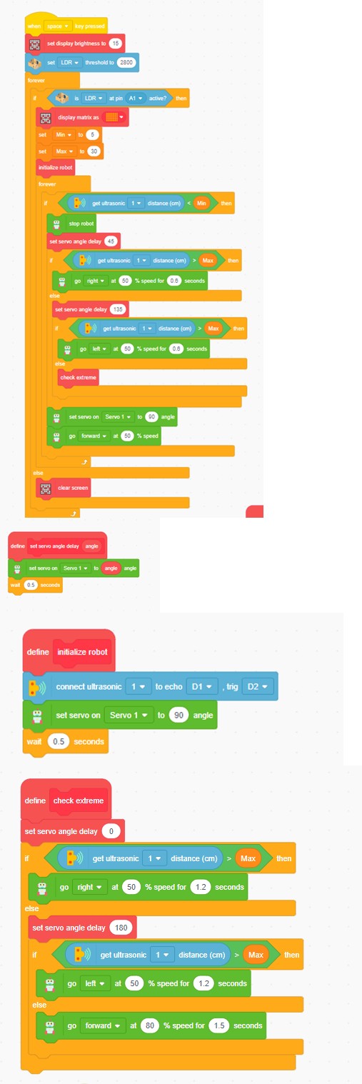
- Activating lights if it’s too dark.
- Quarky patrolling the lab if it’s too dark.
- Opening a door if motion is detected.
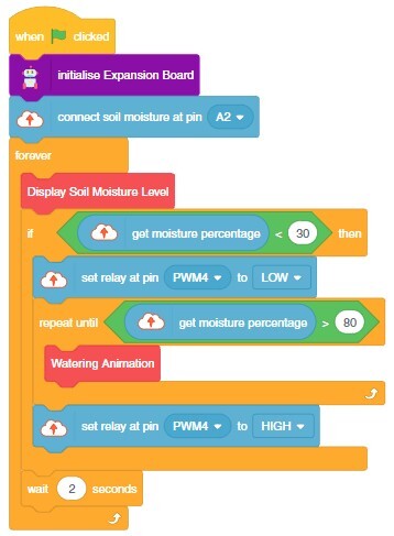
- Monitoring moisture for plant irrigation.
Used STEMpedia’s PictoBlox app for IoT communication.
Configured the system to trigger devices remotely.
Simulated various conditions to test sensor accuracy and system response:
- Lowered light level to activate LED lights or Rover and Lights.
- Simulated dry soil to show low moisture alerts.
- Gave a threshold of high temperature to turn on the Fan.
- When the temperature is below 20°C, the Heater is turned on and internal lights assist in temperature regulation.
- Placed a matchstick nearby to let the Flame sensor detect fire and activate the security system.
Adjusted code and thresholds as needed for reliable automation.
Organized the sensors neatly on the IoT House model.
Labeled each sensor and actuator for clarity.
Recorded observations and ensured all automated responses functioned as expected.
Automated Light Detection System
Automatic Cooling System
Flame Detection System
Drip Irrigation System
Automatic Heating System